Notice: Function _load_textdomain_just_in_time was called incorrectly. Translation loading for the acf domain was triggered too early. This is usually an indicator for some code in the plugin or theme running too early. Translations should be loaded at the init action or later. Please see Debugging in WordPress for more information. (This message was added in version 6.7.0.) in /home4/rucativa/public_html/ssc2.pedroazambujavarela.net/wp-includes/functions.php on line 6170
Graphic statics – Stereotomy Semantic Classification

Graphic statics

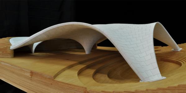
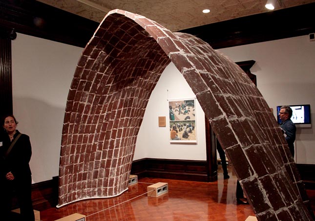
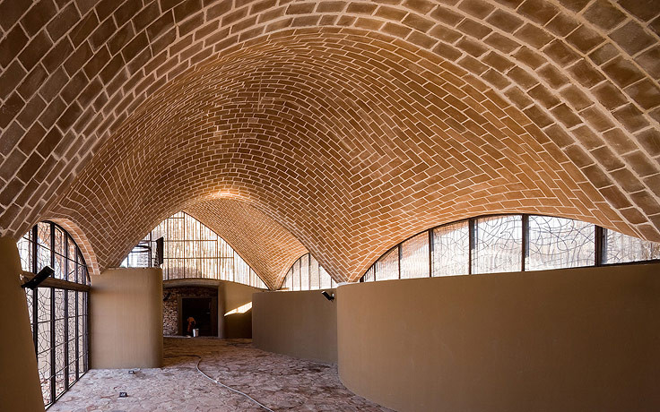
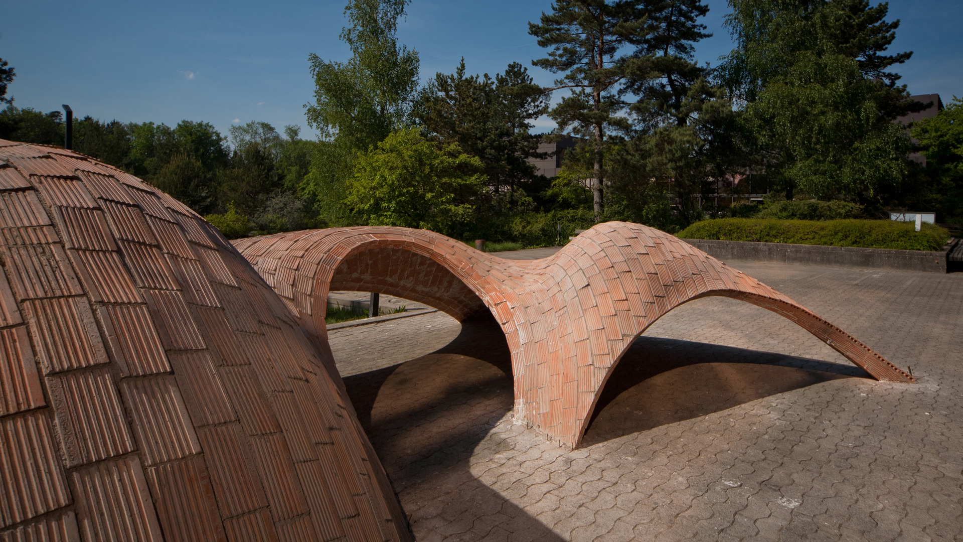
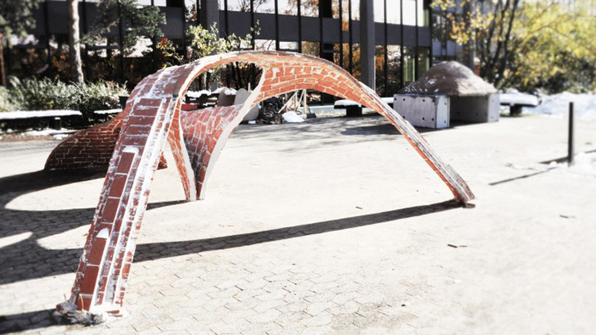
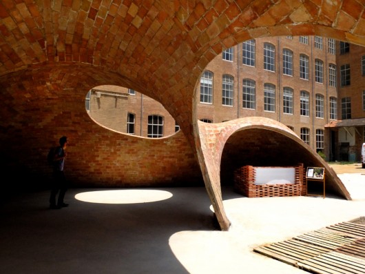
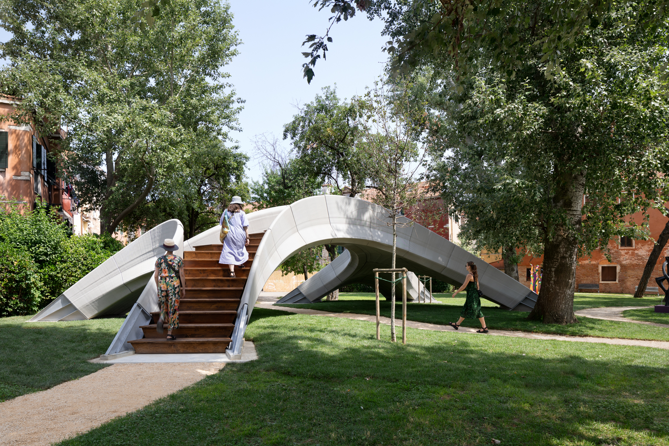
Graphic statics is an intuitive method of both visualizing and determining the forces in structures (Williams and McRobie, 2016) that has its roots in Varignon (1725)โ€™s Nouvelle Mรฉchanique ou Statique in which a force polygon representing the geometry of the structure and a force diagram representing the interaction of forces are linked through geometric constraints (Axel Kilian, 2006), providing a graphic reading of the forces implicit in the structure. This method came to be the most used in engineering until the end of the 19th century with the apex of metal trusses construction; when concrete construction started to gain momentum, other methods based in analytical calculus eventually took over (Kurrer, 2008). With the advent of heavy computation, other applications of graphic statics were possible and, based in Williams (1986) suggestion of reciprocal figures, Block (2009b) creates a framework[1] that allows for rapid and interactive funicular structures design using graphic statics. The most significant software today that allows for the interactive three dimensional surfaces in equilibrium based in graphic statics is RhinoVault, and has been already successfully used in stereotomic projects such as the Armadillo Vault.


[1] This framework is called TNA (Thrust network analysis), and it is the theoretical base behind Matthias Rippmann (2016)โ€™s RhinoVault software used to design funicular shells.
Facets:

Show all Semantics
  • E Equilibrium

    • EA Macro-shape

      • EAA Generation method

        • EAAA Top down

          • EAAAA Constant generatrix

          • EAAAB Varying generatrix

        • EAAB Bottom up

          • EAABA Hanging models

          • EAABB Graphic statics

      • EAB Continuity

        • EABA Segmented

        • EABB Continuous

    • EB Structural functioning

      • EBA Compression only

      • EBB Compression and tension

        • EBBA Tension resistant voussoirs

        • EBBB External reinforcement

      • EBC Tension only

    • EC Surface subdivision

      • ECA One level subdivision

        • ECAA Pattern

          • ECAAA Periodic

            • ECAAAA Developable

            • ECAAAB Constant principal curvature

          • ECAAB Non-periodic

            • ECAABA Topological approach

              • ECAABAA Regular

              • ECAABAB Semi regular

            • ECAABB Space filling polygons

        • ECAB Performative subdivision

          • ECABA Curvature

          • ECABB Aesthetics

          • ECABC Voussoir dimensions

      • ECB Multiple level subdivision

        • ECBA Courses and voussoirs

        • ECBB Micro voussoirs within macro voussoirs

    • ED Foundation

      • EDA Site fixation

        • EDAA Pre-existing static base

        • EDAB Purposed static base

        • EDAC Tensioned springers

        • EDAD Wall or lintel supports

      • EDB Springer

        • EDBA Materiality

          • EDBAA Same as voussoir

          • EDBAB Different material

        • EDBB Geometry

          • EDBBA Subdivision continuity

          • EDBBB Specific design

  • T Tomotechny

    • TA Materialisation Processes

      • TAA Subtractive

        • TAAA 2D cut

          • TAAAA Milling (2D cut)

          • TAAAB Laser

        • TAAB 3D cut

          • TAABA Milling (3D cut)

          • TAABB Saw (3D cut)

          • TAABC Wire cutter

          • TAABD Water jet

        • TAAC 3D carve

          • TAACA Chisel and Mallet

          • TAACB Milling (3D carve)

          • TAACC Saw (3D carve)

      • TAB Additive

        • TABA Material extrusion

        • TABB Binder jetting

      • TAC Formative

        • TACA One-off Mould

        • TACB Reconfigurable Mould

    • TB Centering

      • TBA Temporary

        • TBAA Support structure below

          • TBAAA Extruded grid

          • TBAAB Per-Voussoir

          • TBAAC Along lines

        • TBAB Tensioned voussoirs above

      • TBB Permanent

      • TBC Inexistent (Centering)

        • TBCA Self supported

        • TBCB Additionally supported

    • TC Technical drawing method

      • TCA Two dimensional drafting

        • TCAA Trait

        • TCAB Descriptive geometry

      • TCB Three dimensional modelling

        • TCBA Computerized model

        • TCBB Computational model

  • V Voussoirs

    • VA Material

      • VAA Sustainability

        • VAAA Extraction

        • VAAB Transportation

        • VAAC Processing

        • VAAD Fabrication

      • VAB Structural performance

        • VABA Compression

        • VABB Tension

        • VABC Density

      • VAC Material Typology

        • VACA Subtractable materials

        • VACB Formable materials

        • VACC Additive materials

    • VB Intrados and Extrados

      • VBA Surface

        • VBAA Double Curvature

        • VBAB Single Curvature

        • VBAC Planar (Intrados and Extrados Surface)

        • VBAD Textured

      • VBB Perimeter

        • VBBA Concavity

          • VBBAA Convex

          • VBBAB Concave

        • VBBB Correspondence

          • VBBBA Analogous

          • VBBBB Differentiated

    • VC Contact surface

      • VCA Geometry

        • VCAA Ruled

        • VCAB Planar (Contact Surface)

        • VCAC Composite

      • VCB Friction

        • VCBA Smooth

        • VCBB Rough

      • VCC Mortar

        • VCCA Inexistent (Mortar)

        • VCCB Gap filling

        • VCCC Binding

      • VCD Interlock

        • VCDA Alignment

        • VCDB Sliding prevention

        • VCDC Cantilevering


Posted

by